Pure Resistive AC Circuit
Pure Resistive AC Circuit
The circuit containing only a pure resistance of R ohms in the AC circuit is known as Pure Resistive AC Circuit. The presence of inductance and capacitance does not exist in a purely resistive circuit. The alternating current and voltage both move forward as well as backwards in both the direction of the circuit. Hence, the alternating current and voltage follows a shape of the Sine wave or known as the sinusoidal waveform.
Contents:
- Explanation of Resistive Circuit
- Phase Angle and Waveform of Resistive Circuit
- Power in Pure Resistive Circuit
In the purely resistive circuit, the power is dissipated by the resistors and the phase of the voltage and current remains same i.e., both the voltage and current reach their maximum value at the same time. The resistor is the passive device which neither produce nor consume electric power. It converts the electrical energy into heat.
Explanation of Resistive Circuit
In an AC circuit, the ratio of voltage to current depends upon the supply frequency, phase angle, and phase difference. In an AC resistive circuit, the value of resistance of the resistor will be same irrespective of the supply frequency.
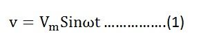
Let the alternating voltage applied across the circuit be given by the equation
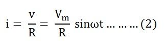
Then the instantaneous value of current flowing through the resistor shown in the figure below will be: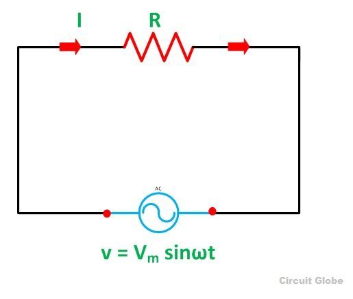
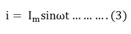
The value of current will be maximum when ωt= 90° or sinωt = 1
Putting the value of sinωt in equation (2) we will get
Phase Angle and Waveform of Resistive Circuit
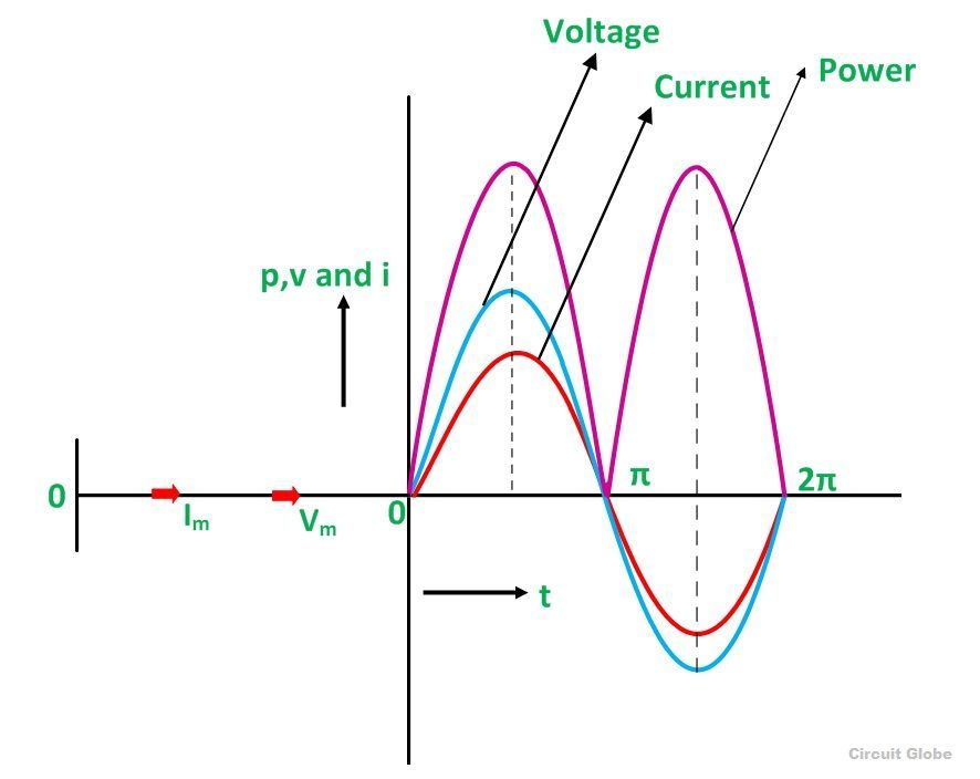
From equation (1) and (3), it is clear that there is no phase difference between the applied voltage and the current flowing through a purely resistive circuit, i.e. phase angle between voltage and current is zero. Hence, in an AC circuit containing pure resistance, the current is in phase with the voltage as shown in the waveform figure below.
Power in Pure Resistive Circuit
The three colours red, blue and pink shown in the power curve or the waveform indicate the curve for current, voltage and power respectively. From the phasor diagram, it is clear that the current and voltage are in phase with each other that means the value of current and voltage attains its peak at the same instant of time, and the power curve is always positive for all the values of current and voltage.
As in DC supply circuit, the product of voltage and current is known as the Power in the circuit. Similarly, the power is the same in the AC circuit also, the only difference is that in the AC circuit the instantaneous value of voltage and current is taken into consideration.
Therefore, the instantaneous power in a purely resistive circuit is given by the equation shown below:
Instantaneous power, p= vi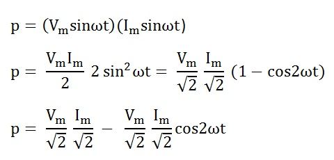
The average power consumed in the circuit over a complete cycle is given by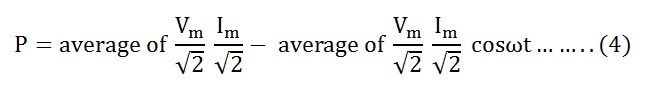 As the valve of cosωt is zero.
So, putting the value of cosωt in equation (4) the value of power will be given by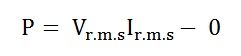 Where,
- P – average power
- Vr.m.s – root mean square value of supply voltage
- Ir.m.s – root mean square value of the current
Hence, the power in a purely resistive circuit is given by:
![]() The voltage and the current in the purely resistive circuit are in phase with each other having no phase difference with phase angle zero. The alternating quantity reaches their peak value at the interval of the same time period that is the rise and fall of the voltage and current occurs at the same time.
The voltage and the current in the purely resistive circuit are in phase with each other having no phase difference with phase angle zero. The alternating quantity reaches their peak value at the interval of the same time period that is the rise and fall of the voltage and current occurs at the same time.
Useful Link:
Pure capacitor : https://divassanjyal.blogspot.com/2025/01/pure-capacitor-circuit.html


Comments
Post a Comment
Thank you for visiting😊