DC Circuit Note
DC
Circuit
Electric Circuit: An electric circuit is a closed path or loop through which
an electric current can flow. It typically consists of a power source (such as
a battery or generator), wires or conductors to carry the current, and one or
more electrical components (such as resistors, capacitors, or light bulbs) that
are connected to the circuit to perform a specific function.
Define DC circuit: The closed path in which the direct current flows is
called the DC circuit.
The current flows in only one direction and it
is mostly used in low voltage applications.
A simple dc circuit is:
Types of DC Circuit
The DC
electric circuit is mainly classified into three groups. They are the series DC
circuit, parallel DC circuit, and series and parallel DC circuit.
DC Series Circuit
A
circuit in which have a DC series source, and the number of resistors are
connected end to end so that the same current flow through them is called a DC
series circuit. The figure below shows the simple series circuit. In the series
circuit the resistors R1, R2, and R3 are connected in series across a
supply voltage of V volts. The same current I is flowing through all three resistor
If V1,
V2, and V3 are the voltage drop across the three resistor R1, R2, and R3 respectively,
then
Let R
be the total resistance of the circuit then
Total
resistance = Sum of the individual resistance.
In such
type of circuit, all the lamps are controlled by a single switch and they
cannot be controlled individually. The most common application of this circuit is for
decoration purposes where a number of low voltage lamps are connected in series.
DC Parallel Circuit
A
circuit which have a DC source and one end of all the resistors is joined to
a common point and the other end are also joined to another common point so that
current flows through them is called a DC parallel circuit.
The figure shows a simple parallel circuit. In this circuit, the three resistors R1, R2, and R3 are connected in parallel across a supply voltage of V volts. The current flowing through them is I1, I2, and I3 respectively.
The
total current is drawn by the circuit
Let R be the total or effective resistance of the circuit, then
Reciprocal
of total resistance = sum of the reciprocal of the individual resistance.
All the
resistance is operated to the same voltage, therefore all of them are connected
in parallel. Each of them can be controlled individually with the help of a
separate switch.
DC
Series-Parallel Circuit
The
circuit in which a series and parallel circuits are connected in series is called
a series parallel circuit. The figure below show the
series-parallel circuit. In this circuit, two resistors R1 and R2 are
connected in parallel with each other across terminal AB. The other three
resistors R3, R4, and R6 are connected in parallel with each other
across terminal BC.
The two
groups of resistors RAB and RBC are connected in series with each other
across the supply voltage of V volts. The total or effective resistance of the
whole circuit can be determined as given below
Similarly Total or effective resistance of the circuit,
Do
you know Electrical and Electronic Engineering are Different:
Let's see
the difference between Electrical and Electronics Engineering :
|
Parameter |
Electrical Engineering |
Electronics Engineering |
|
Definition |
Electrical
engineering is the branch of engineering that deals with the studies of
power generation, transmission, distribution, and utilization at high
voltages. |
Electronics
engineering is the field of engineering that deals with the utilization of
electronic components such as diodes, transistors, etc. to design electronic
circuits and systems. |
|
Current flow |
In
electrical engineering, the electric current flows due to the movement of
electrons in a conductor. Basically, electrical engineering deals with the flow
of electric current in the conductors only. |
In
electronics engineering, the electric current is caused due to flow of
electrons and holes. Electronics engineering deals with the flow of current
semiconductors. |
|
Conducting material |
In
electrical engineering, the conductors (or metals) such as copper, aluminum,
etc. are used as the primary conducting material. |
In
electronics engineering, only semiconductor materials such as silicon,
germanium, etc. are used. |
|
Voltage range |
Electrical
engineering deals with high voltage ranges such as 220 volts in 1-phase, and 440
volts in 3-phases at the utilization end. It also uses higher voltages of the
order of kV for generation, transmission, and distribution purposes. |
Electronics
engineering deals with the range of voltage in mV to a few volts. The typical
voltage ratings used in electronics are 5V, 12V and 24V, etc. |
|
Type of current |
Alternating
current (AC) is used in electrical engineering. |
In
electronics engineering, only direct current (DC) is used. |
|
Power rating |
In
electrical engineering, the function of the electrical system is to handle
a large amount of electrical power. |
Electronics
engineering monitors and controls low electric power. |
|
Device size |
The
electrical devices and equipment are large in size and thus require more
space. |
Electronic
devices are relatively smaller in size. |
|
Examples of devices |
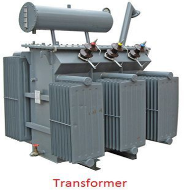
Examples of electrical devices are alternators, generators, transformers,
motors, circuit breakers, isolators, etc. |
Examples of electronic devices are diodes, transistors, SCRs, microprocessors,
integrated circuits, logic gates, etc. |
Define resistance:
Resistance
opposes the flow of current. Resistance is different for different materials. Its
unit is ohms(Ω). Resistance is represented by R.
The formula of calculating the resistance is
R=V/I
Where V
is voltage and I is current
Define One ohm:
Resistance of an object having one ampere is flowing through it when the potential
different is one volt.
Resistance is
directly proportional to length and inversely proportional to cross section
area
R ∝ L………(a)
R ∝ A………(b)
Combing two equation we get,
R ∝ L/A
R= ρ(L/A)
Effect of temperature upon resistance:
Effect of temperature on
resistance of conductor:
The resistances of conductors vary depending on many factors such
as the material of the conductor made up of, the size of the conductor, the
ambient condition, etc. Temperature is also an important factor that changes
the resistance of a conductor.
The effect of temperature on the resistance of the conductor is
directly proportional to each other. The increase in temperature of the
conductor increases its resistance and makes it difficult to flow current
through it. As discussed above, the movement of free electrons creates the flow
of current in the conductor.
Effect of temperature on resistance of semiconductor
By applying temperature to the semiconductor material, the bond
strength between the atoms can be broken and this makes the electrons jump from
the valence band to the conduction band and the conductivity of the
semiconductor increases. Since the conductivity of a body is inversely
proportional to its resistance, hence with the increase in temperature, the
resistance of the semiconductor material decreases.
Effect of temperature on resistance of insulator
On the increasing temperature, the outermost electrons in the
valence band vibrate and this vibration loosens the bond between the electrons
and the nucleus. It provides the possibility of conduction when the valence
band electrons reach the conduction band.
The increase in temperature decreases the forbidden energy gap to
some extent and starts conduction. Hence, at some temperature, insulators
behave as the conductor with the increase in temperature, the conductivity of
the insulators increases and resistance decreases.
There are also some materials having zero resistance, which are
called superconductors. The temperature at which the materials obtain zero
resistance is called the critical temperature of the conductor.
When the relation is directly proportional, i.e, the resistance
increases with the increase in temperature, it is called the positive
temperature coefficient. If the resistance of the body decreases with the
increase in temperature or vice-versa, the temperature coefficient is called
the negative temperature coefficient.
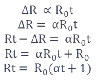
Considering the resistance of the body at 0℃ as Ro Ω
and Rt Ω at t℃.
Therefore, the change in resistance becomes
∆R = Rt – Ro
…………….. (3)
The change in resistance depends on the nature of the conductor
used and from the relation given in equation (3),
∆R ∝ Ro
and ∆R ∝ t℃
Here, α is called the temperature coefficient of the resistance.
Delta to
Star Conversion
Let’s derive the equation for each impedance.
The
given figure shows a delta network having A, B, C terminals with the impedances
R1, R2, R3. The equivalent star connected network with RA, RB &
RC where they are connected to their
corresponding terminals as shown in the figure.
As mentioned earlier, the terminals A, B, C
remains the same, as well as the impedance between them, must remain the same.
Similarly the impedance between terminals B-C
Similarly the impedance between A-CAccording to star network;
RAB = RA + RB
RBC = RB + RC
RAC = RA + RC
Now adding equation (i), (ii) & (iii)
together
Now
subtract equation (i), (ii), & (iii) one by one from equation (iv)
First, Subtract (ii) from (iv)
Similarly
subtracting (i) & (iii) from (iv) results in
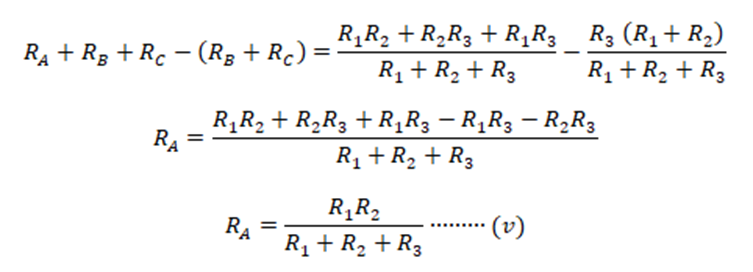
From
the derived equations for star-equivalent impedances RA, RB,
& RC we can conclude the relation between
delta-to-star conversions as; the equivalent star impedance is equal to the
product of the adjacent delta impedances with a terminal divide by the sum of
all three delta impedances.
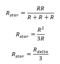
In case all three
Impedances are same in a delta network, the equivalent
star impedance would become
Star to Delta Conversion
Now we are going to convert the
star connected impedance into delta connected impedance. Let’s derive the
equations used for a star to delta conversion.
The
given figure shows star connected impedance RA, RB & RC. While
the required delta equivalent impedance is R1, R2 & R3 as
shown in the figure.
Similarly
multiplying (vi) with (vii) & (v) with (vii)
Now add equation (viii), (ix) & (x)
together
In
order to get the individual equivalent delta impedance, we divide equation (xi)
with (v), (vi) & (vii) separately such as.
Similarly
dividing equation (xi) with (vi) & (vii) separately results in
The
relation between star to delta equivalent impedance is clear from the given
equation. The sum of the two-product of all star-impedances divide by the star
impedance of the corresponding terminal is equal to the delta impedance
connected with the opposite terminal.
Simplifying the equations will lead to
In
case all the star impedances are equal, the equivalent delta impedance would be;
Using the previous equation,
This equation suggests that each equivalent delta impedance is equal to 3 times the star impedance.
OHM’S LAW:
According to Ohm's Law, the current flowing in a conductor is
directly proportional to the potential difference across conductor.
I∝V
where
R is constant called Resistance
Limitations of ohm's law:
1. Ohm's law does not apply to
unilateral electrical components such as diodes as well as transistors even
though they only permit current just to flow in one way.
2. Voltage level will not be constant
with respect to time for non-linear electrical components with properties such
as capacitance, resistance, and so on, making Ohm's law problematic to apply.
3.The relation between V and I depends on the sign of V(+
or -). In other words, if I is the current for a certain V, then reversing the
direction of V keeping its magnitude fixed, does not produce a current of the
same magnitude as I in the opposite direction. This happens for example in the
case of a diode.
4.Ohm’s law is only applicable in metallic conductors. So
it won’t work in the case of non-metallic conductors.
Applications of Ohm’s law in Daily Life:
Ohm’s law can determine the voltage applied in a circuit,
the value of resistance, and the current flowing through the circuit. With the
help of the above three values, we can find the value of other factors like
resistivity and many more. Some daily applications of Ohm’s law:
In fuses: In
order to protect a circuit, fuses and circuit breakers are used. These are
connected in series with the electrical appliances. Ohm’s law allows us to find
the value of the current which could flow through the fuses. If the current
value is too large, then it could damage the circuit and even lead to the
explosion of the electronic device.
To know power consumption: The
electrical heaters have a high-resistance metal coil that allows a certain
amount of current to pass across them to provide the heat needed. Using this
law, the power to be given to the heaters is determined.
To control the speed of fans: By
shifting the regulator to the end from start, we can regulate the speed of the
fans in our houses. By controlling the resistance via the regulator, the
current flowing through the fan is managed here. We can measure the resistance,
current, and thus power flowing via Ohm’s Law for any particular value of the
input.
For deciding the size of resistors: Electric
appliances like electric kettles and irons have a lot of resistors inside them.
In order to provide the necessary amount of heat, the resistors restrict the
amount of current that can flow through them. By using Ohm’s law, the size of
resistors included in them is defined.
Sample Problems
Problem 1: What is the current flowing in a 75
W light bulb connected to 120 V?
Solution:
We
have given the value of power (P = 75W) and value of Voltage (V = 120V).
We
want to find the value of current I.
Using
Ohm’s law,
P = IV
or
I = P
/ V
= 75 / 120
= 0.625 A.
Kirchhoff Current Law
KCL or Kirchhoffs current law or Kirchhoffs first law
states that the total current in a closed circuit, the entering current at node
is equal to the current leaving at the node or the algebraic sum of current at
node in an electronic circuit is equal to zero.
Kirchhoff’s Current Law
In the above diagram, the currents are denoted with i1,i2,i3,i4
,i5and i6. According to the KCL law, the entering currents are i1,i2,i6 and the
leaving currents are i3,i4 and i5. The equation can be written as
i1+i2+i3+ i6 =i3+i4+i5
Kirchhoff
Voltage Law
KVL or Kirchhoff’s voltage law or Kirchhoffs second law
states that, the algebraic sum of the voltage in a closed circuit is equal to
zero or the algebraic sum of the voltage at node is equal to zero.


Numerical problem:
1. If 0.6A current flows through a
resistor shown in figure. Voltage of two points of resistor is 12V. What is the
resistance of the resistor?
Solution:
Here, Current, I = 0.6A
Potential difference or Voltage, V =
12V
Resistance, R =?
According to ohms law questions we
know,
V = IR
Or, R =V / I
=12V / 0.6A
=20 Ω
Ans: 20 Ω.
2. Resistance of an electric iron
50 Ω.4.2A Current flows through the resistance. Find the voltage between
two points.
Solution:
Here, Resistance, R = 50 Ω.
Current, I =4.2 A
Voltage, V =?
From Ohm’s law,
V = IR
= 4.2 × 50
= 210V
Ans: 210V.
3. Let the
resistance of an electrical component remains constant while the potential
difference across the two ends of the component decreases to half of its former
value. What change will occur in the current through it?
Answer
According to Ohm’s law
V = IR
⇒ I=V/R ...
(1)
Now Potential difference is decreased to half
∴ New potential difference Vʹ=V/2
Resistance remains constant
So the new current Iʹ = Vʹ/R
= (V/2)/R
= (1/2) (V/R)
= (1/2) I = I/2
Therefore, the amount of current
flowing through the electrical component is reduced by half.
4.Using KVL and KCL find the branch currents in the given circuit
In loop 1, using KVL
we get










Comments
Post a Comment
Thank you for visiting😊